PROF. P. D. GROVER*
1.0 INTRODUCTION
The role of adopting biomass fueled improved cook stoves in providing comparative convenience to users, control of indoor emissions in domestic sector and fuel savings is well recognized. This is evident from the fact that almost every country in Asia has their own programme of developing and disseminating improved cook stoves (ICS) amongst several million of households who cannot afford the modern clean and efficient fuels. As an example, India with its National Programme on Improved Chulhas, implemented since 1985-86, has so far promoted 28.50 million stoves against an estimated potential of covering 120 million rural and semi-urban households (1). A survey study has shown that an improved chulha saved fuel material equivalent to 210 kg of coal/soft coke, valued at Rs. 388 per year. In terms of kerosene, the savings work out to about 40 litres per chulhas per year, valued at Rs. 343 per household.
So far the thermal efficiency of these improved stoves has approached 25 to 35 percent, compared to 6 to 10 percent for traditional stoves. This implies that these stoves are still 65-75 percent inefficient and account for a tremendous energy wastage, considering the gigantic number of such appliances deployed in the domestic sector. The question that arises at this stage is whether these indicative efficiency and inefficiency numbers can be reversed. Presently, the answer may be an elusive one but the fact remains that the efficiencies have to be improved if we aim at sustainable development and take into consideration the negative role of green house gases being generated by these inefficient ICS. By any wood energy projection model, the fact remains that the wood energy is here to stay. Many people in Asia and in the world will continue to depend on wood to fuel their energy needs. Therefore, there is a need to maximize its utilization through efficient appliances. One is optimistic as high efficiencies have been obtained in similar industrial systems. For instance, a steam generation plant with 88% thermal efficiency has been reported working on rice husk producting 10 TPH of high pressure steam with 2000 kg/hr. of rice husk, at SEDA Distillery in Saluzzo (Italy), operational since 1983 (2).
Even at domestic level, a typical multipurpose wood fueled appliance, known as thermo kitchen, providing cooking, space heating and utility hot water can reach an overall thermal efficiency of 75-80%. A large variety of such models are being used in the villages of Europe, some of them using direct flame combustion while others have the inverted flame (down draft) combustion system (2).
However, these appliances are very large in their thermal output and also very expensive. The need is, therefore, to scale down these technologies used in such appliances and bring them to play their role in cookstoves at reasonable and affordable costs. The future cookstove development
programmes should be directed in this direction so as to have a stove in near future with an overall high performance. At present, such a stove may be termed as a "Dream Stove".
* Ex. I.I.T. Delhi
IRP Energy Consultants
44, Community Centre
East of Kailash, New Delhi - 45 India
2.0 REVIEW OF STOVE DEVELOPMENT
The developmental approach to cookstove design has been shifting between fuel efficient to emission efficient stoves. Between this shift, one of the development strategies adopted on a large scale was to improve their heat transfer efficiency and provide a chimney to take away the smoke. Although this approach helps in improving the indoor air quality but the quality of combustion still remains questionable in most of the designs. Incomplete combustion in such stoves not only tends to deposit products of incomplete combustion, mostly carbon soot and tars, in the flue ducting and chimney but also those products which remain undeposited escape into the atmosphere and are potential green house gases. The time has arrived that we should further improve these stoves and move up the energy ladder from presently developed ICS to high performance cook stoves (HPC).
A HPC stove should be both fuel and emission efficient. Both these aspects are so inter-related that an emission efficient stove will inherently have an efficient consumption of fuel. In other words, a high performance stove implies that other than CO2 and water vapours as unavoidable emissions of complete combustion, the associated undesirable emissions as products of incomplete combustion (PIC) should be minimized or totally eliminated. These also include avoidance of thermal emissions (called thermal pollution) and particulate emissions. The traditional cookstoves, because of their very low efficiency, emit more than 10% of their carbon as PIC comprising varying amount of tars. In addition, about 100 to 180 g of carbon monoxide and 7.7 g of particulate matter are also emitted per kg. of wood. In comparison, one kg of charcoal used for cooking in metal stoves emits 250 - 350 g of carbon monoxide, but less (2.4 g) of particulate matter. These PIC emissions do increase when loose biomass or cowdung are deployed for cooking in these stoves.
Furthermore, it should be understood that the efficient use of wood is much more eco-friendly than the use of more efficient and convenient fuels, such as kerosene and LPG, so far as emission of carbon dioxide is concerned which is the principal source of global warming. The CO2 emission factor for fuel wood is placed as 5.1 kg CO2/GJ compared with corresponding figures of LPG of 76.6 kg CO2/GJ and for natural gas as 49.5 CO2/GJ (3).
3.0 STRATEGY FOR DEVELOPMENT
The development approach for HPC requires a directed focus towards the production of emission efficient stoves, irrespective of whether the emissions take place either indoor or into the outdoor atmosphere. Emissions are emissions and must be prevented to safeguard the environment. This approach will automatically provide a large saving of fuels. For sustainable development, this becomes mandatory because wood consumption for energy is going to stay with us whether we want it or not. According to FAO report,(3) the wood fuel consumption in Asia is projected to go upto 11,600 PJ in 2010 from 8,304 PJ in 1994 at the prevailing consumption growth rate of averaging 2.1% per annum. The stove development strategy should, therefore, be primarily directed towards getting complete combustion of fuel to avoid emissions along with maximum reduction of heat losses to the atmosphere, unless these heat losses are needed towards space heating as an additional utility. These process conditions would provide clean and total combustion of biomass leading to the development of high performance stoves. A stove with these features is being termed as a Dream Stove.
Understanding the combustion process provides the ability to manipulate it for maximum thermal efficiency and minimum pollution production. Before the concept of a "Dream Stove" is initiated it is pertinent to review the related aspects of biomass combustion.
4.0 BIOMASS COMBUSTION
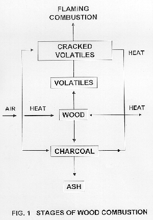
The combustion of solid fuel encompasses a series of complex reactions whereby carbon and hydrogen in the fuel chemically react with atmospheric oxygen to form CO2 and H2O while liberating usable heat. The mechanisms of combustion include:
particle heating and drying, pyrolysis, gas phase
precombustion reactions, combustion reactions, char oxidation reactions
and post-combustion reactions. Without going into their details we will
consider only a general model as shown in figure - 1 comprising stages
of wood heating and drying, solid particle pyrolysis, gas phase reactions
and char oxidation reactions.
Stage - 1 Heating and Drying
Initially the wet biomass fuel particle is heated to the point when its pyrolysis begins. This stage of heating and drying is dominated by physical reactions and greatly influenced by the fuel moisture content. Higher moisture content reduces the energy availability of the fuel but enhances the heating process due to higher fuel thermal conductivity.
Stage - 2 Pyrolysis
Once the fuel particle is dried and heated to temperatures approaching 225 - 3250 C, thermal breakdown (pyrolysis) of hemicellulose starts continuing to pyrolyse other biomass constituents (cellulose and lignin) as the temperature reaches towards 5000 C. Pyrolysis releases volatiles and gaseous products and solid char, the proportion of these heavily depends upon particle size, ultimate temperature, and rate and time of heating.
Stage - 3 Gas Phase Reactions
The volatiles produced during pyrolysis are a vast array of products and undergo complex array of sequential reactions in order to achieve their total combustion. In order to initiate and sustain clean and total combustion of these volatiles, the larger molecular constituents of these volatiles have to be fragmented into lower order molecules by maintaining high temperatures, turbulence and residence time in the combustion chamber. Normally in a typical stove these processes are left to the geometry of its combustion chamber and flue gas pathways. Before completion of these processes if these flaming gases are quenched by taking away heat by a cook pot, these volatiles remain unreacted and produce smoky flame. Therefore, providing proper conditions or incorporating any additional facility in the stove for fragmentation of these large molecules (tars etc.) is the key to getting clean and total combustion.
Stage - 4 Char Oxidation reactions
During pyrolysis char is also produced which gets combusted with air by surface reactions. Initially as CO and H2 are generated which inturn provide clean burning. The char oxidation reactions are much slower than the gas phase flaming reactions. This hot char can also be utilized for the thermal cracking or fragmentation of tarry volatiles to obtain clean combustible gases as practiced in down draft gasifiers.
5.0 COMBUSTION CONCEPT IN A DREAM STOVE
The purpose of reviewing the combustion mechanism
is to try to incorporate separate stages of combustion in a stove. Instead
of having only one combustion chamber to allow all the competing reactions
of various stages to take place, the proposal is to incorporate more than
one stages in a stove to manipulate total combustion. Furthermore, this
conceptual stove should have only minimum number of stages so as not to
complicate its design and operation. The concept being proposed is not
new but it is similar to a system comprising a combination of downdraft
gasifier and gaseous burner, both combined in a single cookstove. Accordingly,
for a "Dream Stove" a combination of only two stages is proposed. First
stage is for heating, drying and pyrolysis of fuel with minimum amount
of air followed by a second stage in which the gaseous pyrolytic products
are thermally cracked and then burnt clean with additional secondary air.
The thermal cracking of tars is facilitated by passing the volatiles over
hot and burning charcoal kept in the second stage. This implies that this
stove is first started as charcoal stove in the second stage, with left
over charcoal by the previous operation, followed by initiating controlled
combustion in the pyrolysis chamber, stage - 1. Though it may seem slightly
complicated but the advantages obtained in overall performance over weigh
this extra effort as one is expected to get clean charcoal fire in a wood
fired stove. Conceptually the process is shown in Figure - 2.
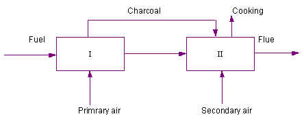
Figure - 2. Concept of combustion in a "Dream Stove"
Stage - I . Heading, Drying & Pyrolysis Stage - II .Thermal Cracking of Tar and Clean Combustion.
The advantages of staged combustion are many. Because
of destruction of tars and other larger molecules of volatiles the combustion
obtained is clean and PIC are eliminated. Apart from clean and complete
combustion, the other main benefit of stage combustion is the reduction
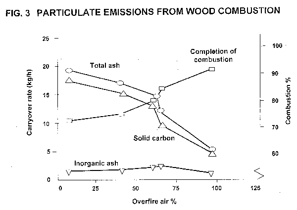
of emissions especially those of particulates. Junge, (4) has demonstrated
that particulate carry over in biomass combustion is minimized during staged
combustion. Staged combustion amounts to the using of sub-stoichiometric
quantities of air in pyrolytic stage with excess air being introduced as
secondary air. The optimum percentage of air introduced as over fire or
secondary air appears to be in 55 - 60% of total air range. The effect
of overfire air on carry over of particulates in Industrial applications
is given in figure - 3.
6.0 EXPECTED THERMAL EFFICIENCY OF A DREAM STOVE
In order to arrive at a reasonable value of thermal
efficiency of a "Dream Stove" it is desirable to first calculate the maximum
theoretical efficiency possible under ideal and pseudo practical conditions.
The data of such an exercise is presented below:
EXERCISE - I
BASIS:
(a) Wood fuel with 15% moisture and 3% ash.
(b) No losses other than heat losses from the flue gases.
(c) Complete combustion of wood with total recovery of heat to utility.
| Percentage Excess air
(%) |
(Sensible heat + latent) |
(%) |
|
0 |
|
|
|
|
|
|
|
|
|
|
|
|
|
|
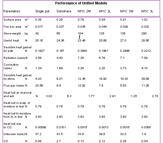
Table - I shows that with control of excess air about 80 percent thermal efficiency of a stove can be obtained. It may be mentioned that staged combustion system would need lesser excess air than that required for a conventional single stage stove. Apart from major losses through the flue gases, there are other heat losses which cannot be eliminated but can be minimized by taking up appropriate measures. In order to quantify other various losses, the data developed by Sharma (5) and reproduced as Table - II is taken into consideration.. Analyzing this data, it can be concluded that the major heat losses in ICS are the unknown losses amounting to as high as 40 percent for a single pot stove. These are basically due to incomplete combustion. Other major losses are due to sensible heat gained by multipot stoves amounting to as high as 39 percent when the useful heat component varies from 25 to 29 percent. Apart from achieving complete combustion, it is also desired to minimize these losses which can be achieved by using proper light-weight and effective insulation. For this insulation an optimum use of ceramic fibre blanket of 25 mm thick is recommend for a "Dream Stove".
Ceramic fibre blankets have very low thermal conductivity,
about 16% of any dense refractory material, are light weight (65 - 192
kg/m3) and extremely cost effective. The relative cost of ceramic
fibre blanket of 25mm thickness is about 20 percent of an equivalent 135
mm dense refractory. Ceramic fibres can withstand temperatures up to 13000
C compared to mineral wool upto 7000 C and glass fibre upto
4500 C. Use of ceramic fibre can drastically improve the performance
of a cookstove.
Table IIResults of the thermal performance of various stoves(5)

Considering the data given in Tables I
& II and based
on experience gained with Industrial furnaces working on wood, it is possible
to restrict the various heat losses from cook stoves to the values given
in Table III . Also
the techniques that are deployable to attain these values are provided.
Table - III Maximum limits of Heat losses expected from A "Dream Stove"
| Avenue of heat losses |
|
Techniques Deployable | |
| Flue gases |
|
Minimize excess air
Maximize heat transfer Gases outlet temp. » 1500 C |
|
| Radiation losses from stove body |
|
Proper insulation with enclosed fire | |
| Sensible heat gained by stove |
|
Minimizing the stove weight and use of effective and light weight insulation around hot zones. | |
| Heat losses through ash and charcoal handling |
|
Minimized by enclosed operation and preheating the air over hot ash | |
| Unknown losses |
|
Minimized by careful operation | |
| Useful heat |
|
Balance | |
This above mentioned value of 65% thermal efficiency can also be justified by comparing a "Dream Stove" with a combined system of a gasifier (80 - 85% efficiency) and gas combustion burner with cooking efficiency of 80%, providing an overall efficiency in the range of 64 to 68 percent. Compared to present ICS efficiency of about 25-30 percent, this may seem like a dream but with innovative approach it should be achievable. Detailed analysis of existing stoves, design of stoves with staged combustion, intensive prototype and extensive fields testing programmes have to be continued to develop this "Dream Stove".
7.0 PROPOSED DESIGN OF A "DREAM STOVE"
Many design configurations of "Dream Stove" are possible. Some of these
are conceptualized and given in figure-4. All of these may not initially
give desired thermal efficiencies but one fact is clear that they will
provide complete combustion and a significant reduction of PIC. Multipot
approach (figure - 4b) should provide efficiencies approaching the anticipated
values compared to the single pot stoves (figure - 4a).
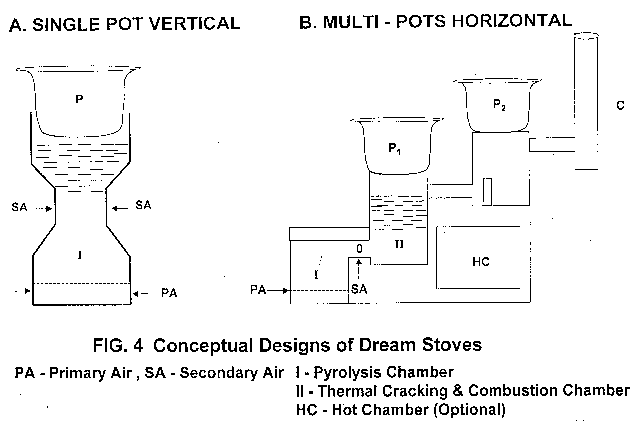
In all these configurations, chamber I is meant for drying and pyrolysis of biomass operating under starved air producing pyrolysis gases and wood charcoal. The pyrolysis gases are allowed to pass through chamber - II which is basically a charcoal burning chamber meant to crack the volatiles before these are combusted.
The stove operation is first started in the chamber II using left over charcoal from from the previous operation using any suitable ignitor and cooking operation is initiated. Immediately afterwards pieces of wood are added into the chamber I and ignited with small pieces of wood. A damper is needed for chamber I to minimize the ingression of primary air. Another damper for secondary air will also be a useful addition. Once the cooking operation is complete, the dampers are closed to stop the pyrolysis process and the charcoal produced is not allowed to burn but retained for the next operation. In case the cooking operation is required for a lengthy period of time a part of hot charcoal from chamber - I can be manually transfered to chamber - II . At the end of cooking, quenching of charcoal can also be done by a mild sprinkling of water.
Along with charcoal some refractory pieces should also be added which will offer additional surface area for the cracking of volatiles. The quantity and sizes of these refractory pieces can be optimized by the developers to provide clean and complete burning of volatiles. It may be reiterated that the proposed "Dream Stove" is to provide absolute clean combustion similar to the one experienced by the burning of L.P.G. with minimum manipulation by the users.
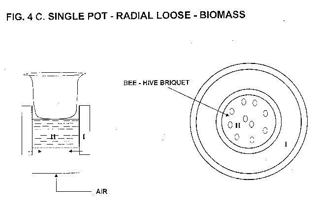
In case loose biomass is utilized as fuel, configuration (4-c) is an
ideal design. Since the char produced in this stove shall be in powder
form, this will have to be briquetted using 30 percent moist clay into
lumps or as beehive briquettes using hand moulds. Any type of convenient
operation or design can be adopted but the basic requirement of any stove
is that two chambers have to be provided to get clean and complete combustion.
8.0 COST ESTIMATION
Out of three configurations proposed in figure - 4, the single pot vertical (4-a) and multipot horizontal stoves (4-b) can be built in traditional materials coupled with modern insulating materials. Accordingly, these are comparatively cheaper than the single pot-radial stove for loose biomass which has to be built in metal. Since A "Dream Stove" has to be not only efficient but should also be made available at affordable costs, the cost estimates for only single and multipot configurations have been carried out.
The cost estimation of any new appliance is normally based on the cost
of similar systems for which sufficient experience is available. Accordingly,
in this particular case the cost of a multi-pot stove is based on a similar
three pot ICS known as "Rohini" which is fairly popular in India (6). The
proposed two pot "Dream Stove" is similar to "Rohini" model, given in figure
-5 except for the following modifications. The modified "Rohini" stove
converted into a Two Pot "Dream Stove" is shown in Figure - 6.
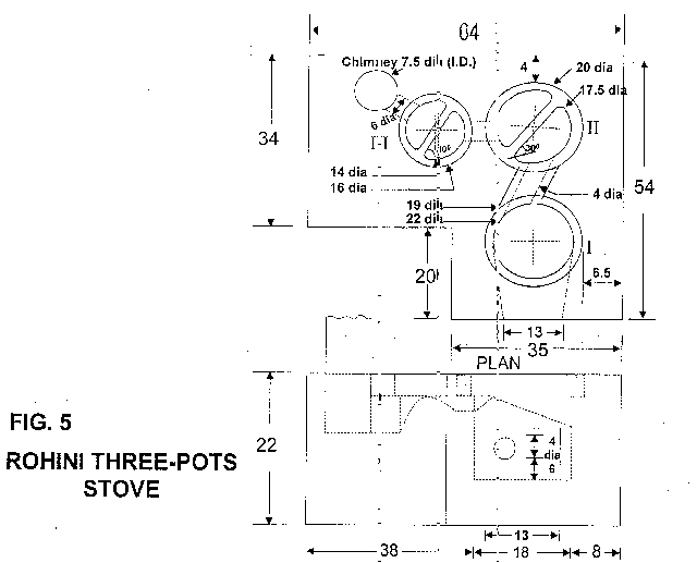
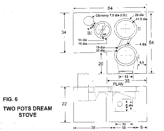
Modifications:
1. The first pot chamber of "Rohini" stove is converted into Stage - 1 of the "Dream Stove" mean for pyrolysis of wood by providing a proper side damper, closing the top end with an insulated enclosure and providing a suitable grate for proper distribution of primary air.
2. The second pot chamber of Rohini stove is converted into stage - II of the "Dream Stove" meant for cracking and combustion of pyrolytic gases by providing a charcoal grate and used as first chamber for cooking.
3. The pot three of Rohini stove acts as the second pot for cooking in the "Dream Stove".
4. To conserve heat losses, all stages I , II , III and intermediate flue ductings are fitted with 20 mm thick fired clay liners backed by 25mm thickness of ceramic fibre blanket. This technique would avoid the heating of stove body and considerably reduce the sensible heat losses to heat up the large mass of the stove.
5. Holes for secondary air entrance with damper are provided between
stage I and II .
The main body of the stove can be constructed in three possible types of
material. These are:
(i) Entirely made from local clay as in Rohini model
(ii) Made in cement mortar construction for longer life and low maintenance
(iii) Made in local clay with outer body cladding of 1.5 mm thick steel for enhanced life and clean appearance
(iv) Made in cement mortar with cladding of 1.5mm thick m.s. plate for maintenance free operation.
Based on the dimensions of the two pot "Dream Stove" shown in figure - 6, the quantities of different materials deployed for construction and their unit costs are given in Table IÑ
Table IÑ Materials of Construction and Costs
|
|
|
kg/m3 |
Rs./Kg. |
(Rs.)* |
| Clay (Mud) |
|
|
|
|
| Cement Concrete |
|
|
|
|
| Fire clay
liners 20 mm thick |
|
|
|
|
| Blanket 25 mm thick
(ceramic fibre) |
|
|
|
|
| Steel Casing 1.5 mm thick |
|
|
|
|
| Chimney Steel |
|
|
|
|
| Chimney ceramic |
|
|
|
|
*(Based on Indian Cost Data. US $ = Rs. 43.5)
In addition, the stove shall have two air dampers; one each for primary and secondary air and two grates for the stages I - II . The estimated costs of these accessories is around Rs. 50. Having inventoried the materials required (Table IÑ ) for the construction of two pot stove, the cost estimates for various options are now provided in Table - Ñ
Table - Ñ Cost Estimates Of Two Pot "DREAM STOVE"
|
|
(Rs.) |
(Rs.) |
(Rs.) |
| clay body, ceramic pipe chimney without ms casing |
|
|
(US $ = 20) |
| cement body ceramic pipe chimney without ms casing |
|
|
(US $ = 22) |
| Extra ms casing |
|
|
(US $ = 9.70) |
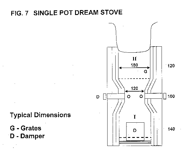
8.1 SINGLE-POT-STOVE
The cost of a two pot stove is rather high and is
unaffordable by majority of users. In that situation a single pot stove
without ms casing and chimney will be cheaper and so desirable to develop.
Accordingly, the quantities and type of materials required for a single
pot stove, based on the design given in Figure-4a, have also been determined
and are given in Table - ÑI
.
Table: VI Material Costs for Single Pot DREAM STOVE
|
|
|
|
| Fire clay liners | 0.0047 m3 |
|
| Ceramic fibre blanket | 0.24 m2 (25 mm thick) |
|
| Clay | 0.01 m3 |
|
| Cement | 0.01 m3 |
|
| Steel casing (1.5 mm Th.) | 0.4 m2 (optional) |
|
| Two dampers and one charcoal grate |
|
|
The overall cost of single pot stove of various options is given in Table - VII.
Table - ÑII Cost Estimates of Single Pot Stoves
|
|
(Rs.) |
(Rs.) |
(Rs.) |
| Stove in clay with ceramic liners |
|
|
(US $ 8.00) |
| Stove in cement with ceramic liners |
|
|
(US $ 8.62) |
| ms casing (optional) |
|
|
(US $ 3.25) |
The single pot "Dream Stove" (figure-7) could be
made available at a cost ranging from $ 8.0 to $ 12.0 a piece. Like any
other items, this cost can be reduced by having mass production and using
local materials having the same thermal and mechanical properties. So the
development activities should also be directed towards selecting cheaper
materials for construction without sacrificing their essential properties
to restrict heat losses. The heat losses directly affect the desired temperatures
within the stoves which in turn have direct bearing on the quality of combustion.
The main emphasis for the development of "Dream Stove" has to be on the
core aspect of quality combustion and its related fallout on emission quality.
9.0 DESIGN OF COOKING POT
Another major aspect in cookstove development is
to have a cooking pot which can offer optimum surface area for heat transfer
and can cook more than two food items in multiple sub-compartments. These
separate food compartments are arranged in such a manner that the steam
evolved from the bottom most compartment can condense on the upper compartment
thereby providing fuel economy in a similar manner as in multi-effect evaporators
in Industry. This is another area of development which is important and
should be adopted as an integral part of "Dream Stove" development.
10.0 CONCLUSIONS
By any stretch of dreaming and imagination, it is not impossible to have a biomass cook stove with total combustion and an approachable efficiency of around 65 percent, and also made available at an affordable cost. The basic concept to be adopted is to aim for total fuel combustion. The total fuel operation, desirable for micro and macro level control of atmospheric pollution, leading to better life for all the inhabitants of this universe.
11.0 REFERENCES:
1. Ministry of Non-Conventional Energy Sources, Govt. of India, Annual Rep., 1998-99.
2. Biomass Combustion Technologies, CNRE guideline No. 1, pp.66-68, FAO publication, 1988.
3. Trossero, Miguel. A, Ed., The role of wood energy in asia, FAO working paper, FOPW/97/2, Nov., 1997.
4. Junge, D.C, Design Guideline Handbook for Industrial Boilers Fired with Wood and Bark residue fuels, Oregon St. uni., Corvallis, Oregon, 1979.
5. Sharma, S.K, Improved Solid Biomass Burning Cookstoves, RWEDP, Field Document No. 44, pp.66, Sept., 1993.
6. Sharma, S.K. Improved Solid Biomass Burning Cookstoves, RWEDP, Field Document No. 44, pp.88, Sept. 1993.